
Tiêu chuẩn TCVN 10304:2014 “Móng cọc – Tiêu chuẩn thiết kế” xuất bản đã khắc phục được những nhược điểm chí tử mà người thiết kế xây dựng gặp phải và ngầm hiểu với nhau mà TCXDVN 205:1998 do lỗi chính tả hay chỉ dẫn chưa rõ ràng. Điều quan trọng hơn là sức chịu tải của cọc dự báo theo tiêu chuẩn mới cho giá trị cao và gần với thực tế thí nghiệm nén tĩnh của hàng vô số công trình trong suốt hơn chục năm của thực tế dùng móng cọc.
Như vậy, về cơ sở lý thuyết đã rõ ràng. Nhiệm vụ của người kỹ sư thiết kế giờ là ứng dụng tiêu chuẩn mới trong công tác dự báo sức chịu tải của cọc bằng cách xây dựng công cụ (phần mềm, bảng tính Excel…). Sau đây xin trình bày các bước ứng dụng TCVN 10304:2014 một cách thực tế nhất cho 2 loại cọc phổ biến là cọc khoan nhồi và cọc đóng/ép.
1. Tính toán sức chịu tải theo vật liệu cọc
Hầu hết trường hợp thiết kế kết cấu thực tế là cọc chịu lực nén đúng tâm do đài truyền vào từ công trình bên trên, vật liệu cọc bêtông cốt thép thường. Dùng công thức tính toán như cấu kiện bêtông chịu nén đúng tâm của TCVN 5574:2012 như sau:
$$P_{VL}=\varphi\left(R_bA_b+R_{sc}A_{st}\right)$$
Diễn giải công thức:
$A_{st}$ là tổng diện tích cốt thép dọc trong cọc
$A_b$ là diện tích bêtông trong cùng tiết diện cọc
$R_{sc}$ là cường độ tính toán về nén của cốt thép
$R_b$ là cường độ tính toán về nén của bêtông cọc, bằng cường độc tính toán gốc của bêtông nhân với các hệ số điều kiện làm việc $\gamma_{cb}.\gamma’_{cb}$ như sau:
$\gamma_{cb}=0,85$ kể đến đổ bêtông trong khoảng không gian chật hẹp của hố khoan, ống vách
$\gamma’_{cb}$ kể đến phương pháp thi công cọc, trường hợp phổ biến là cọc khoan nhồi tương ứng trường hợp ghi trong TCVN 10304:2014 là Trong các nền, việc khoan và đổ bêtông vào lòng hố khoan dưới dung dịch khoan hoặc dưới nước chịu áp lực dư (không dùng ống vách) $\gamma’_{cb}=0,7$. Các trường hợp khác xem mục 7.1.9 của tiêu chuẩn.
Với cọc bêtông cốt thép đúc sẵn đóng, ép, các hệ số $\gamma_{cb}=\gamma’_{cb}=1$.
$\varphi$ là hệ số giảm khả năng chịu lực do ảnh hưởng của uốn dọc, theo TCVN 5574:2012:
- Với $\lambda\leqslant28,\varphi=1$
- Với $28<\lambda\leqslant120, \varphi=1,028-0,0000288{\lambda}^2-0,0016\lambda$
Khi tính toán thiết kế kết cấu theo cường độ vật liệu, xem cọc như một thanh ngàm cứng trong đất tại chiều sâu cách đáy đài một khoảng: $l_1=l_o+\frac{2}{\alpha_{\varepsilon}}$
$l_o$ là chiều dài đoạn cọc kể từ đáy đài đến cao độ san nền
$\alpha_{varepsilon}=5\sqrt{\frac{kb_p}{\gamma_cEI}}$
$k$ là hệ số tỷ lệ, phụ thuộc vào loại đất bao quanh cọc theo bảng A.1 của TCVN 10304:2014
$E$ là module đàn hồi của vật liệu làm cọc (bêtông)
$\gamma_c=3$ là hệ số điều kiện làm việc đối với cọc độc lập
$\frac{2}{\alpha_{varepsilon}}$ không được vượt quá chiều sâu đến mũi cọc từ đáy đài $h$
$\lambda=\frac{l_1}{r}$ là độ mảnh của cọc, $r=\sqrt{\frac{I}{A}}$ là bán kính quán tính của tiết diện cọc.
Lưu ý với cọc thí nghiệm, cường độ chịu nén gốc của bêtông cọc cần nhân với hệ số điều kiện làm việc $\gamma_{b2}=1,1$ do tính chất tải trọng nén tĩnh là tạm thời, ngắn hạn.
Trong trường hợp thiết kế kết cấu cọc dùng bêtông cốt thép dự ứng lực, sức chịu tải theo vật liệu cọc tính toán theo hướng dẫn của TCVN 7888:2008.
2. Tính toán sức chịu tải cọc theo đất nền
Sức chịu tải của cọc theo đất nền xác định đối với cọc chịu nén như sau:
$$Q_a=\frac{\gamma_o}{\gamma_n}\frac{R_{c,u}}{\gamma_k}-W_c$$
$R_{c,u}$ là sức chịu tải trọng nén cực hạn
$W_c$ là trọng lượng bản thân cọc có kể đến hệ số độ tin cậy bằng 1,1
$\gamma_o$ là hệ số điều kiện làm việc, kể đến yếu tố tăng mức độ đồng nhất của nền đất khi sử dụng móng cọc, lấy bằng 1 đối với cọc đơn và lấy bằng 1,15 trong móng nhiều cọc
$\gamma_n$ là hệ số tin cậy về tầm quan trọng của công trình, lấy bằng 1,2; 1,15 và 1,1 tương ứng với tầm quan trọng của công trình cấp I, II và III ( Phụ lục F của tiêu chuẩn)
$\gamma_k$ là hệ số độ tin cậy theo đất xác định theo điều 7.1.11 của tiêu chuẩn
Trong thực hành thiết kế xây dựng hiện nay phổ biến tính toán sức chịu tải cọc theo kết quả thí nghiệm xuyên tiêu chuẩn (SPT) dùng 2 công thức Meyerhof và công thức của Viện kiến trúc Nhật Bản như sau:
Công thức Meyerhof:
Sức chịu tải trọng nén cưc hạn:
$$R_{c,u}=q_bA_b+u\sum{f_il_i} (kN)$$
$q_b$ là cường độ sức kháng của đất dưới mũi cọc $q_b=k_1N_p$
$k_1$ là Hệ số, $k_1=40h/d\leqslant400$ với cọc đóng/ép và $k_1=120$ với cọc khoan nhồi
$h$ là chiều sâu hạ cọc
$N_p$ là chỉ số SPT trung bình trong khoảng 1d phía dưới mũi cọc và 4d phía trên mũi cọc
$f_i$ là cường độ sức kháng của đất theo thân cọc
- trong các lớp đất rời $f_i=k_2N_{s,i}$
- trong các lớp đất dính $f_i={\alpha}c_{u,i}$
$k_2$ là hệ số lấy bằng $2,0$ với cọc đóng/ép và bằng $1,0$ với cọc khoan nhồi
$\alpha$ là hệ số xác định theo biểu đồ trên hình G.2 của tiêu chuẩn
$N_{s,i}$ là chỉ số SPT trung bình của lớp đất thứ i trên thân cọc
$c_{u,i}$ là cường độ sức kháng cắt không thoát nước của lớp đất thứ i trên thân cọc $c_{u,i}=6,25N_{c,i}(kPa)$
$N_{c,i}$ là chỉ số SPT trong đất dính của lớp đất thứ i trên thân cọc.
Công thức của Viện kiến trúc Nhật Bản:
$$R_{c,u}=q_bA_b+u\sum{\left(f_{c,i}l_{c,i}+f_{s,i}l_{s,i}\right)}$$
$q_b$ là cường độ sức kháng của đất dưới mũi cọc, xác định như sau:
- Khi mũi cọc nằm trong lớp đất rời $q_b=300N_p$ cho cọc đóng/ép và $q_b=150N_p$ cho cọc khoan nhồi
- Khi mũi cọc nằm trong lớp đất dính $q_b=9c_u$ cho cọc đóng/ép và $q_b=6c_u$ cho cọc khoan nhồi
$f_{s,i}$ là cường độ sức kháng trung bình trên đoạn cọc nằm trong lớp đất rời thứ i $f_{s,i}=10N_{s,i}/3$
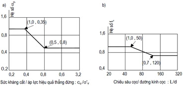
$f_{c,i}$ là cường độ sức kháng trung bình trên đoạn cọc nằm trong lớp đất dính thứ i $f_{c,i}=\alpha_pf_Lc_{u,i}$
$\alpha_p$ là hệ số điều chỉnh cho cọc đóng/ép và $f_L$ là hệ số điều chỉnh theo độ mảnh $h/d$ của cọc đóng, bằng 1 cho cọc khoan nhồi, xác định như các biểu đồ sau của tiêu chuẩn:
$l_{s,i}$ là chiều dài đoạn cọc nằm trong lớp đất rời thứ i
$l_{c,i}$ là chiều dài đoạn cọc nằm trong lớp đất dính thứ i
$N_p$ Đối với các loại đất cát, nếu trị số $N_p>50$ thì chỉ lấy $N_p=50$, nếu trị số $N_{s,i}>50$ thì lấy $N_{s,i}=50$
Đối với nền đá hoặc cuội sỏi trạng thái chặt, khi $N_p>100$ thì lấy $q_b=20MPa$ cho cọc đóng/ép và cọc khoan nhồi có biện pháp làm sạch mũi cọc tin cậy và bơm vữa ximăng gia cường đất dưới mũi cọc.
Thông thường đối với nền có nhiều lớp đất dính dọc theo thân cọc, giá trị sức chịu tải đất nền tính theo công thức Nhật Bản thường lớn hơn công thức Meyerhof. Tư vấn thiết kế nên chọn giá trị làm sức chịu tải dự báo theo một trong hai công thức trên, từ đó quyết định giá trị tải trọng thí nghiệm nén tĩnh max làm căn cứ điều chỉnh cho cọc đại trà sau này.
3. Kiểm tra khả năng chịu tải của cọc
Theo quy định của TCVN 10304:2014, tải trọng nén dọc trục tác dụng lên cọc cần so sánh với sức chịu tải tính toán theo vật liệu và theo đất nền ($Q_a$) như tính toán ở trên.
Tải trọng công trình truyền lên móng là tải trọng tính toán (có hệ số vượt tải) theo tiêu chuẩn Việt Nam, do tiêu chuẩn tính toán theo phương pháp Trạng thái giới hạn.
4. Kết luận
Cách thực hành tốt nhất là lập bảng tính Excel tính toán sức chịu tải theo đất nền tại từng độ sâu mũi cọc so với mặt đất, từ đó có thể vẽ biểu đồ sức chịu tải cọc theo chiều sâu hạ cọc và người thiết kế xây dựng lựa chọn chiều sâu hạ mũi cọc để được sức chịu tải hợp lý.
Có thể tham khảo bảng tính Excel lập theo vật liệu và theo đất nền.