Pile bearing capacity according to TCVN 10304:2014 | Fundamentals for Structural Engineering
The published code TCVN 10304:2014 “Pile foundation – Design standards” has overcome the fatal weaknesses that construction designers encounter and implicitly understand each other that TCXDVN 205:1998 due to spelling errors or unclear instructions. More importantly, the predicted load-bearing capacity of piles according to the new standard gives high values and is close to the actual static compression test of countless works during more than ten years of actual use of pile foundations.
Thus, the theoretical basis is clear. The task of the design engineer is now to apply the new standard in the work of predicting the bearing capacity of piles by building tools (software, Excel spreadsheets…). The following are the steps to apply TCVN 10304:2014 in the most practical way for 2 common types of piles: bored piles and driven/pressed piles.
1. Calculating the bearing capacity according to pile material
In most cases of practical structural design, the piles are subjected to the central compressive force transmitted from the foundation from the above construction, the pile material is usually reinforced concrete. Use the calculation formula as the concrete member subjected to central compression of TCVN 5574:2012 as follows:
Formula explanation:
is the total longitudinal reinforcement area in the pile
is the concrete area in the same pile cross-section
is the calculated compressive strength of the reinforcement
is the calculated compressive strength of the pile concrete, equal to the original calculated strength of the concrete multiplied by the working condition coefficients as follows:
=0.85 including concrete pouring in the narrow space of the borehole, casing
regarding the pile construction method, the common case is bored pile corresponding to the case recorded in TCVN 10304:2014: In foundations, drilling and pouring concrete into the borehole under drilling solution or under water under residual pressure (without using casing) =0.7. For other cases, see section 7.1.9 of the standard.
For precast reinforced concrete piles, driven and pressed, the coefficients =1.
φ is the coefficient of reduction in bearing capacity due to the influence of longitudinal bending, according to TCVN 5574:2012:
for
for
When calculating structural design based on material strength, consider the pile as a rigid rod embedded in the ground at a depth of:
is the length of the pile from the bottom of the foundation to the ground level
k is the proportionality coefficient, depending on the type of soil surrounding the pile according to table A.1 of TCVN 10304:2014
E is the elastic modulus of the pile material (concrete)
=3 is the working condition coefficient for independent piles
not exceed the depth to the pile tip from the bottom of the pile cap
is the slenderness of the pile, is the radius of inertia of the pile cross section.
Note for test piles, the original compressive strength of the pile concrete needs to be multiplied by the working condition coefficient. Because the nature of static compressive loads is temporary and short-term.
In case of designing pile structures using prestressed reinforced concrete, the load bearing capacity according to pile material is calculated according to the instructions of TCVN 7888:2008.
2. Calculate pile load bearing capacity according to Soil
The load bearing capacity of piles according to ground is determined for compressed piles as follows:
is the ultimate compressive load bearing capacity
is the self-weight of the pile including the reliability factor of 1.1
is the working condition factor, taking into account the factor of increasing the uniformity of the ground when using pile foundations, taken as 1 for single piles and taken as 1.15 for multi-pile foundations
is the reliability factor of the importance of the project, taken as 1.2; 1.15 and 1.1 corresponding to the importance of level I, II and III projects (Appendix F of the standard)
is the reliability factor according to the soil determined according to Article 7.1.11 of the standard
In current Structural Engineering practice, it is common to calculate the pile bearing capacity based on the results of standard penetration tests (SPT) using the two Meyerhof formulas and the formula of the Japan Institute of Architecture as follows:
Meyerhof formula:
Ultimate compressive load capacity:
is the soil strength under the pile tip
is the coefficient, for driven/pressed piles and k1=120 for bored piles
h is the pile depth
is the average SPT index in the range of 1d below the pile tip and 4d above the pile tip
is the soil strength along the pile body
in loose soil layers
in cohesive soil layers
k2 is the coefficient taken as 2.0 for driven/jacking piles and as 1.0 for bored piles
α is the coefficient determined according to the diagram in Figure G.2 of the standard
is the average SPT index of the i-th soil layer on the pile body
is the undrained shear strength of the i-th soil layer on the pile body
is the SPT index in the cohesive soil of the i-th soil layer on the pile body.
Formula of the Architectural Institute of Japan:
is the soil resistance strength under the pile tip, determined as follows:
When the pile tip is in the loose soil layer for driven/jacking piles and for bored piles
When the pile tip is in the cohesive soil layer for driven/jacking piles and for bored piles
is the average resistance strength on the pile section located in the i-th loose soil layer
is the average resistance strength on the pile section located in the i-th cohesive soil layer
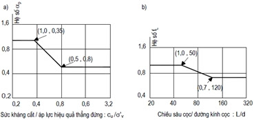
is the adjustment factor for driven/jacking piles and is the adjustment factor according to the slenderness h/d of the driven pile, equal to 1 for bored piles, determined as the following charts of the standard:
is the length of the pile segment in the i-th loose soil layer
is the length of the pile segment in the i-th cohesive soil layer
For sandy soils, if the value , then only take , if the value , then take
For compacted rock or gravel foundations, when , take MPa for driven/pressed piles and bored piles with reliable pile tip cleaning measures and cement mortar injection to reinforce the soil under the pile tip.
Normally, for foundations with many layers of cohesive soil along the pile body, the value of the soil bearing capacity calculated by the Japanese formula is often greater than the Meyerhof formula. the Structural Engineer should choose the value as the predicted bearing capacity according to one of the two formulas above, from which they will decide on the maximum static compression test load value as the basis for adjusting the mass piles later.
3. Check the load-bearing capacity of the pile
According to the regulations of TCVN 10304:2014, the axial compressive load acting on the pile needs to be compared with the calculated load-bearing capacity according to the material and the ground () as calculated above.
The load of the structure transmitted to the foundation is the calculated load (with overload factor) according to Vietnamese standards, because the standard is calculated according to the Limit State method.
4. Conclusion
The best practice is to create an Excel spreadsheet to calculate the load-bearing capacity according to the ground at each pile tip depth compared to the ground surface, from which a graph of the pile load-bearing capacity according to the pile depth can be drawn and the construction designer can choose the pile tip depth to get a reasonable load-bearing capacity.
You can refer to the Excel spreadsheet created according to the material and Soil.