
Post-tensioned structure (PT) has now become popular for civil works and applied in construction design in many different fields, from apartments, offices to commercial centers or garage. The article would like to share a few experiences and personal knowledge gained in the process of working to help the design engineers can accelerate the design of PT slab in a simple way as well as offer an overview of this type of structure for investors and architects designing the building.

Part 1 introduces an overview of the characteristics of a post-tensioned reinforced concrete structure and design features using PT slab structure.
Part 1: Overview of PT slab
1.1.1. General requirements
The basic objective for the operation of the structural designer is to be safe, used normally and most reasonably in economics. Safety is understood as the ability to withstand design loads (the largest load according to the prescribed design standards) without being damaged in excess of the allowed threshold, also known as the first limit state (TTGH1). The ability to use is achieved when the structure works normally throughout its life, also known as the second limit state (TTGH2). Economy shows a high rate between the value achieved when applying a design plan compared to the cost.
In addition, the legality of the design record is also an important factor. Design consultancy must ensure the regulations set by the State standards. However, current standards are often outdated compared to actual construction techniques, especially with post-tensioned concrete structures. The provisions of Vietnamese standards are outdated and incomplete. Therefore, the application of foreign standards is necessary, also in accordance with the characteristics of the first -stressed tendon material that is entirely imported.
1.1.2. Characteristics of concrete compared to other materials
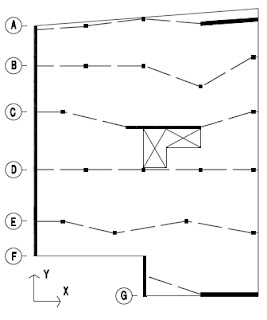
Try an example to compare 3 types of materials: concrete, steel, glass to find out the characteristics of concrete materials. Examples of a slab box as shown in Figure 1.1.1
Normal use (TTGH2) requires hammock level not exceeding the allowed threshold. Safety is measured by the load that causes cracks for the glass: The first crack will immediately spread and destroy materials. The crack occurs in the load generation of tensile stress on the surface to reach the characteristic value for the material of the glass, at a certain point.
With glass, it is essential when designing is determining the exact stress at the points on the slab surface, due to the different working of the glass compared to other materials when the load increases. Therefore, the exact model of geometry and pillows must directly affect the results of stress analysis.
If the slab area is designed with steel material, TTGH2 of the slab is determined by the hammock due to long -term load. Safety is determined by the hammock in excess of the instantaneous load limit (with the load coefficient).
The long -term hammock occurs when there is a flexibility of steel material at a local location, when the stress has exceeded the melting limit of the material. The reliability of the design depends on the accuracy of the specified stress at the points.
The basic content of the steel structure design is that after selecting the slab thickness and the position of the pillow, it will conduct the calculation to check if the calculation stress is less than the limit value of the material. This is the basic difference of the steel structure design compared to the concrete structure as shown below.

Figure 1.1.1
The design of the concrete slab structure consists of 2 basic items: (i) on working conditions (TTGH2), the hammock and width of the crack within the allowed limit (ii) under the effect of instantaneous loads (with the over -load coefficient), the slab plate is not destroyed.
The determination of local stress is not significant in calculating the hammock and width of the crack below the working load. The heterogeneity of concrete material and a few small cracks makes the structural analysis according to the usual elastic model is incorrect. In addition, conventional concrete floors are modeled and designed according to conventional transmission lines, unlike glass and transmission steel, clearly defined from calculated analysis.
In the example, the two options for the line of weight transmission as shown in the figure. The second picture, the slab is modeled as a strip with a rhythm from the A to the wall B. The structural engineer is the person who specifies the line to transmit the weight to these two pillows. With this transmission line, the reinforcement is arranged to ensure safety will be the lower layer steel as shown in the picture. Wall C is not in this conventional transmission line, but in fact it is involved in the load and the slab generates tensile stress on the upper surface of the wall C. Therefore, the designer must place the reinforced steel structure of the upper layer around the wall C to control the cracking under the working load (standard load).
Structural reinforcement is indispensable in the reinforced concrete structure, used for the purpose of improving the working capacity of the structure and depends very much on the experience of the structural engineer, its main task is to ensure:
– Conventional loading line by conventional line structural engineer. In fact, it is possible to transmit larger load than the limited value by the design standard
– The width of cracks at the working load within the allowed limit. Often the design standards specify the minimum reinforced steel content in each concrete section to ensure that the concrete section is only flexible. It is the ability to have a certain deformation before and when it exceeds its intensity before being destroyed. This helps to redistribute the load in the slab and mobilize the work of the slab according to the chosen lane of the chosen lane.
Figure 1.1.2 Examples of steel cases are composed of the deployment of weight transmission lines. The effect of the centralized load is distributed on the width of the conventional transmission line through the reinforcement of the structure distributed under that concentrated load. This reinforcement ensures the transmission line between the two walls A and B can be specified as the selected structural engineer. Figure 1.1.2 (b) illustrates structural reinforcement to prevent cracking for the concave corner of the slab.

Figure 1.1.2 – Structural reinforcement
Conventional transmission line is necessary for concrete slab because the layout of reinforced slab decides the direction and the magnitude of the load capacity of the slab. There are usually more than 1 single transmission line, and this is the backbone of the structural system of the whole project.
The concrete structure does not behave sensitive to local stress. Figure 1.1.3 (a) shows the moment distribution from the analysis results of the slab elastic analysis (excluding the horizontal expansion coefficient Poisson). When designing reinforced steel, it is usually calculated to bear the simple moment as shown in Figure 1.1.3 (b). The layout of the reinforcement in that moment on the surface is not important as long as the quantity. The reason is that the sabotage slab along the flexible joints and these lines will mobilize the entire reinforcement through it to work.

This is a different feature of concrete design Moment Total. The distribution and local value at each strip width is not important. Different from glass and moment steel should be checked at each point, concrete structure only needs to be concerned about the total torque value on the cross -section of the range width. Therefore, when calculating the slab with a finite element, even smaller split, the total Moment result on the slab is no different. You can verify the Safe software.
With PT structural construction design, as well as glass and steel, the stress test is needed in the standard load. With glass testing to avoid cracks, with steel to check local flexible and long -term hammock. With concrete is controlled (allowed cracks to appear. In practice, the design stress in concrete is an assumption because it is calculated from the total moment across the slab section. In reality the stresses around the pillow are much larger and most of them exceed the crack limit of concrete. The design stress has therefore significantly pointed out the range of cracks that appear in that area rather than the actual stress value.
1.1.3. PT DESIGN Features
As above, the characteristics of Structural design reinforced concrete is to indicate the line of loading or the slab. Pre -stress concrete structure is more complicated because of adding input parameters and alignment in calculations.
Designing post-tensioned structure according to TTGH1 and TTGH2 includes control of the parameters: (i) The amount of post-tensioned cables, and (ii) the tendon altitude. Steel reinforcement usually complements the slab will be determined by these two parameters.
In the regular slab, each slab strip is indicated that there will be only one calculated reinforcement result. In the first stress slab, each structural engineer will give a different result because the two parameters are quantity and the first chosen tendon orbit is usually different.
In general, the reinforced concrete slab is designed according to the following process:

1.2.1. Calculation model
Select the calculation method
There are 3 methods of slab calculation: “Simple frame”, “equivalent frame” and “finite element” (PTHH). In the simple frame method (SFM), the frame calculated to the tactor hardness and the relevant slab from the exact geometric size of the components. In the calculation, it does not mention the 2 -way bending effect of the slab.
The equivalent frame method (EFM) is the improvement of SFM in which the relative hardness of the column and the slab is adjusted to include the 2 -way oral effect. This method is therefore more accurate than SFM and is most commonly used to calculate the slab so far.
Input requirements for both PP EFM and SFM in terms of geometric size, load, boundary conditions of the slab design strip are the same. These 2 PPs are close and gives safety results. The accuracy of these 2 pps decreases when the slab has a thick tank (with beams, hats, etc.) and column nets in 2 directions are not aligned, perpendicular.
Current method of teaching method structural engineers Used most through software such as Safe, Adapt slab Pro, RAM Concept … This is a method for higher accuracy due to the slab division into small elements, each behavior of the material attribute, geometry, position in the slab, linked to the surrounding elements and thus the work of bending in 2 exact ways.
1.2.2. Choose the slab – line of weight transmission
This is the most basic step in the process of slab structural design. The structure of the worker structure when the weight of yourself and the other loads on the slab at all points is transmitted to the pillows (columns, walls) according to the lines of weight. For example, for a slab with a complex column grid as follows:

The loading line is drawn through the pillows of columns, walls in 2 directions X, Y. This is the hypothesis that the slab transmission of the pillows is the original selected by the designer. Can be selected as in the following images:

Then each load line will have a slab transmission area like the following drawings, this area will create a slab strip, this is familiar in Safe. The boundary of the two slab strips is the average lines between adjacent load lines on the same direction X or Y. Requires all strips on one direction to cover the slab area. Some construction design software such as Adapt slab Pro automatically divide the boundaries of strips after drawing loads.


Now each slab strip will be considered as a frame beam of the equivalent frame method and those beam sections (perpendicular to the load line) is the computing section used for the slab design step later. Usually select dangerous sections: in the middle of the beat and two sides of the knee like Figure 1.2.7.

1.2.3. Analysis calculation
After dividing the slab into strips, conduct analysis in one of the three methods above.
Equivalent frame method
This construction design method states the space problem on the flat frame problem.
Separating each slab strip, along with the boundary conditions of the pillow (columns, walls), the slab load acting on the transmission area into an equivalent frame and conducting independent calculation of that frame. Figure 1.2.8 shows the example of separating the slab B in the X direction, which has simplified the model to bring back the beams equivalent to the simple sections: straight and level -level cross sections. Some softwareStructural designAs Adapt-PT allows automatically simplifying the frame from the complex slab surface with high accuracy.


Method of finite element
This PP only needs a single space model, different from the equivalent frame PP to calculate the slab of the slab, to calculate all frames corresponding to each slab strip. When using software calculated by PTHH, the structural engineer still draws the assumptions as mentioned above to get the total moment values on the computing sections.
The advantage is that it is possible to use PPHH to choose the lines and the slab strip. Take a look at the diagram on Figure 1.2.1 about the optional design step. Figure 1.2.10 is the result of the software showing the loading flow to the pillow. The arrows are perpendicular to the plane with the largest cutting force in the slab, the length of the arrow represents the magnitude of this cut.


(The above charts are the result of elastic analysis)
These zero lines are the actual boundaries of the slab and lines in the direction X, dividing the slab strip in this line is the most ideal in terms of economy and using materials with crazy premises like this. If compared to Figure 1.2.5, the transmission line is selected as the original is close to reality and therefore relatively reasonable.
1.2.4. Design
The benefit of the division of the slab is only to care about the total moment value at each calculation section of that range to calculate the reinforcement for the entire section of that cross section. Note that in this width of reinforcement is not important as long as the total reinforcement area is sufficient to bear the total moment as presented at the beginning. Figure 1.2.12 is an example of the Moment chart for the B slab strip, at the computing sections in the pillow and between the rhythm of 1-2. In the picture, the moment of distribution is changed along the width of the computational section. Moment value designed is the sum of the moments distributed on one section (the area of the moment chart). For example, in the axis pillow 2, the total moment to calculate the steel will be 281KNM.

1.2.5. Design drawing layout (structural detailing)
After calculating reinforcement for the slab strips, the structural engineer needs to arrange reinforcement appropriately to ensure the working slab work as the design hypothetically selected.
Ordinary slab
Many construction design standards such as ACI, AS still have regulations on reinforcement arrangement in the band between columns and rhythm strip. With the slab premises with complex shapes and mesh, this way is not good. Here are a few layout suggestions for the most reasonable:
-The trying to arrange reinforcement according to the strip width as the Moment chart is distributed in Figure 1.2.12. For example, negative reinforced steel at the 2 -axis pillow will be arranged mostly around the column area that has the chart of the peak value. Meanwhile, in the middle of the rhythm, the lower layer reinforcement is arranged evenly.
-The entire reinforcement is calculated in the slab around the column with the border column. With the columns between the majority of reinforcement required in the slab around the column. The width of the slab around the column depends on the selection of the structural engineer as above, which can accept this width equal to half of the width of the slab.
-In other points, the minimum amount of reinforcement must be arranged, often prescribed by the standards and distance. This is to limit cracking due to shrinkage and due to temperature changes.
PT slab
Arranging regular reinforcement and PT cables in the Calculated section of PT slab are relatively freely than normal slab. Some initial layout suggestions can be referenced as follows:
-The reinforcement layer on both directions is concentrated in the column end. This strip width for PT slab is smaller for the usual slab as prescribed above.
-The freedom of steel reinforcement is the most convenient for construction.
-The freestyle of PT cables is the most convenient for construction and ensures a minimum of 2 tendon to pass through the column in 2 directions. The maximum distance of the tendon is 8 times the slab thickness.
-In the slab areas with average compressive stress less than 0.7MPa according to calculations, supplements need to be supplemented with often structured to limit cracks due to shrinkage and temperature.
Reinforced steel structure
In addition to the limited role in cracking, it also plays a role in ensuring the actual work as chosen by the lines of the load (as mentioned in part 1.1.2). Một số cốt thép cấu tạo như quanh lỗ mở có thể trình bày dưới dạng chi tiết điển hình. Tuy nhiên phần lớn cốt cấu tạo là dostructural engineerindicated, so their experience and qualifications are highly required here to reflect the correct behavior of the slab structure under the effect of the load.
Usually the reinforcement layout is structured on the pillows not to mention in the assumptions transmission lines, such as the reinforcement under the centralized load in the example stated in the first part. In the design of PT slab construction, the structure needs to be arranged in the area due to geometry or the construction conditions do not arrange enough tendon to ensure the minimum compression force.