
Civil columns are subjected to eccentric compression in two directions in space – oblique eccentricity: The bending moment values along two perpendicular axes M2, M3 are both significant. However, the calculation and design of oblique eccentricity columns is relatively complicated, requiring a large amount of calculation. Currently, popular construction design software such as ETABS can calculate the design of oblique eccentricity problems using the interactive diagram method of column cross-section (interactive diagram surface $N−M_2−M_3$). However, the results of the design of oblique eccentricity columns in ETABS according to foreign standards often give larger results than those of Vietnamese standards. To ensure economy, avoid waste and avoid having to ask the investor for permission to apply foreign standards, the design engineer needs to apply Vietnamese standards for oblique eccentricity problems. The most convenient way is to create a spreadsheet or software based on the available algorithm according to the regulations of TCVN 5574:2012 “Concrete and reinforced concrete structures – Design standards”. This article presents a relatively convenient spreadsheet method in practice according to the method of Professor Nguyen Dinh Cong in the document “Calculation of reinforced concrete column cross-section” for the most common construction design case: rectangular cross-section columns with reinforcement distributed along the perimeter.

1. Establish an interaction diagram according to the Plane Eccentric Compression problem
First consider the plane eccentric compression problem with the bending moment direction along the edge h of the section as shown in the diagram below:
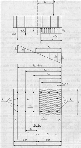
Calculate the stress for each row of steel bars along the direction of edge h, with the i-th row of steel bars as shown in the drawing, using the formula of TCVN 5574:2012
$$\sigma_i=\frac{\sigma_{s,cu}}{1-\frac{\omega}{1,1}}\left(\frac{\omega}{\xi_i}-1\right)$$
in which controlled $-R_{sc}\leqslant\sigma_i\leqslant{R_s}$
$\omega=0,85-0,008R_b$
$\xi_i =\frac {x} {h_ {oi}}$
$R_ b $: design compressive strength of concrete
$R_ {sc} $: design Compressive strength of reinforcement
$R_s $: design tension strength of reinforcement
$\sigma_ {s, cu} $: The limit stress of reinforcement in compressive zone, taken by $\sigma_ {s, cu} = 400 $ MPa corresponding to the case of regular columns and temporary load (including wind load) and special load (earthquake).
By increasing the height of the compression zone from 0.1h to h, the design engineer will obtain a point on the interaction curve corresponding to the internal force pair (M*,N) according to the calculation formulas from the stresses as follows:
$N=R_bbx-\sum{\sigma_iA_i}$
$M^*=0,5R_bbx(h-x)-\sum{\sigma_iA_iy_i}$
$y_i $ is the distance from the center of the first reinforcement to the center of the cross section, the + sign + corresponding to the reinforcement on another side with the compression force.
The maximum value of the vertical force N in the interactive chart is the ability to withstand the center of the section:
$N_o=\varphi\left(R_bA_b+R_{sc}A_{st}\right)$
$\varphi $: axial bending coefficient $\varphi=1,028-0,0000288{\lambda}^2-0,0016\lambda$ when the slenderness of column: $\lambda=l_o/r$ meet $28<\lambda\leqslant120$
Radius of inertia of column cross section r=0.288<Small side of column cross section>
$l_o = {\psi}H $ is the design length of the column
$H $ is the height of the column
$\psi$ is the coefficient taken on the basis of analyzing the deformation diagram of the actual structures as follows:

The problem applied in construction design is the test problem: Arrange the reinforcement in the column section along the perimeter, from which calculate to draw the points of the interaction diagram for each direction. Due to the large amount of repetitive calculations, it is possible to use programming in VBA language in Excel spreadsheet to perform the stress calculation formulas and the pairs (M*,N) as above.

2. Convert the problem of bending in two directions to equivalent plane bending
For each combination of internal column forces, we have pairs of internal forces (N, M2, M3). After considering the effect of bending along two directions, the bending moment increases from M2, M3 to M∗2, M∗3 by multiplying the longitudinal bending coefficient $\eta_2,\eta_3$
$$M_2^*=\eta_2Ne_{o2}, M_3^*=\eta_3Ne_{o3}$$
According to the method proposed by Professor Nguyen Dinh Cong, depending on the value of M∗2, M∗3, it can be converted to the problem of eccentric compression in direction 2 or 3.
$M_x^*=M_2^*, M_y^*=M_3^*$
$e_a=e_{a2}+0,2e_{a3}$
$h=C_3; b=C_2$
$M_x^*=M_3^*, M_y^*=M_2^*$
$e_a=e_{a3}+0,2e_{a2}$
In there:
$c_2, c_3 $ is the column cross section dimension in the Moment $M_2, M_3 $
The values $e_o = M/N, e_a $ is the static eccentricity and random eccentricity corresponding to the internal force pairs (M,N) in each direction 2, 3.
For each internal force pair of the internal force combination under consideration, calculate the equivalent bending moment value (convert the oblique eccentric compression problem to the plane eccentric compression problem):
$$M_{tđ}^*=M_x^*+m_oM_y\frac{h}{b}$$
For $m_o = 0.4 $ when $x_1 = \frac {n} {R_bb}> h_O $
$m_o=1-\frac{0,6x_1}{h_o}$
Conducting a comparison of each point with the coordinates of the inner force of $(M_ {td}^*, N) $ with the interactive chart in the direction 2 or 3: If the internal force point is under the interactive line $(M^*, N) $, the column is capable of bearing the inner force complex being considered.

🎁 The convenient Excel is convenient for the design engineer according to the above process here.
Reference:
- TCVN 5574: 2012: “Concrete structure and reinforced concrete. Design code”
- “Calculation of reinforced concrete column section” – GS. Nguyen Dinh Cong – Construction Publishing House 2006