
Unlike the upper floors (sky floors), the slab on grades structure is in direct contact with the ground like the ground floor or basement. Every house has this floor but it is often designed in a “prescription” style based on experience. The problem is that young people with no experience can prescribe medicine without understanding 🤣. Many unfortunate cases have occurred due to improper calculation of the load-bearing capacity, such as the weak ground below sinking, leading to cracked floors, peeling tiles… causing loss of aesthetics, negative psychological effects, and even danger to residents. Please share a simple practice on this construction design issue.
=======================================
💎Slab on grade Details
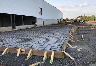
Experience in residential buildings for generations, the simplest is that the floor of a normal house is structured as 🗻Photo 1:

The load-bearing structure of the floor (under the tiles and mortar) is unreinforced concrete, even using broken brick concrete or sand-cement mortar. Under the load-bearing layer is an artificial sub-grade of sandy soil, then the natural soil. The floor structure is independent and does not transfer the load to the foundation (under the foot of the column or load-bearing wall).

💎In case the ground is too weak
💎Design Codes
💎Calculate the settlement

The second settlement calculation diagram is the Linear Deformation Layer with finite thickness, according to section 4.6.8.b) and appendix C.1.8 of the Standard, applied when the ground is quite strong, that is when:
– In the area where settlement has not stopped, there is a good soil layer with deformation modulus E≥100MPa
– The floor has a large size (width >10m) AND the deformation modulus of the soil layers is E≥10MPa
The calculated thickness of this finite deformation layer is determined according to appendix C.1.9 of the Standard.
💎practical Structural Engineering steps
1️⃣Determine the elasticity coefficient of the foundation K:
The settlement load p is considered to be evenly distributed on the floor, including the weight of the floor itself and the Sub grade layers. (See Example)
Settlement s is calculated by one of the two methods: Addition of layers or Linear deformation layer with finite thickness
K = p/s
To verify the field data for the value of K, use the compression table test on the Sub grade foundation in the correct order of layers as designed.
2️⃣Calculation model of the foundation floor
The calculation diagram is a table on an elastic foundation, using structural design software according to finite elements, such as Etabs, Safe..
The foundation coefficient K can be taken as constant or changed to distribute by area on the floor area. The foundation coefficient K diagram changes more accurately with the actual operation of the foundation floor because the settlement value changes: the largest at the center of the foundation and gradually decreases towards the edge. Design engineers can refer to the way to divide the K coefficient zone as in 🗻Photo 4, in each zone K is taken according to the settlement at the dot point of that zone.

3️⃣Load distribution on the floor in the following cases: whole floor and offset
If the calculation diagram of the foundation coefficient has a constant value over the entire floor area, the load on the whole floor will not cause internal force. In reality, the load (people, warehouses, vehicles, etc.) never acts on the floor with the same value. To simplify the calculation diagram of the structure design, it is possible to load (live load) offset according to the column grid.
According to the cases: checkerboard and strip in each direction as 🗻Photo 5.

🎁Example of practical calculation:


🔲Case 2, the foundation coefficient changes with the maximum value Kg=850T/m3 at the corner of the floor, corresponding to the smallest settlement of 15mm. The load combination evenly distributed throughout the floor causes uneven settlement, the largest being 37mm at the center of the foundation (🗻Photo 8). This is more suitable for the actual working of the foundation floor structure. The smaller internal force leads to the reinforcement only needing Φ12a50.

=======================================
The floor design process can be applied to raft foundations on natural ground, the working method is identical. The only difference is the load: The raft foundation mainly bears the column foot load concentrated on the surface. So it is using a skill that is applied to many Structural Engineering applications.